The circuit explained below can be used for detecting and converting the very low radio frequencies or VLF in the atmosphere to audible sound.
A huge number of general-coverage shortwave receivers start with the AM-broadcast band and rise in frequency to around 10 meters, or 30 MHz.
This typical tuning arrangement neglects a majority of the interesting and uncommon signals found below the standard broadcast band.
This is where the proposed VLF converter circuit comes to aid.
Wireless and electrical frequencies in the atmosphere that are transmitted in the lower frequency range between 3 kHz and 30 kHz are known as VLF or very low frequency.
There are a number of rare signals that is audible on frequencies below 15 kHz. Such a signal is the dit-dah wave that is a slow and comes in two tone. It is just strong to be detected on a fairly short antenna. Heavy signals like electrical storms and powerful lightning can be received in those frequencies as crunching, whistling crackling noises way before the thunderstorm strikes.
On frequencies more than 15 kHz, one would expect to detect several of the following signals; Loran, Military, several foreign broadcasts, diverse CW signals and in certain places a number of beacon and CW signals between 160 kHz and 190 kHz delivered by testers using 1 W transmitters. Most of the regulated transmitters have occupied the airways for a few hundred miles to be detected by other VLF’ers.
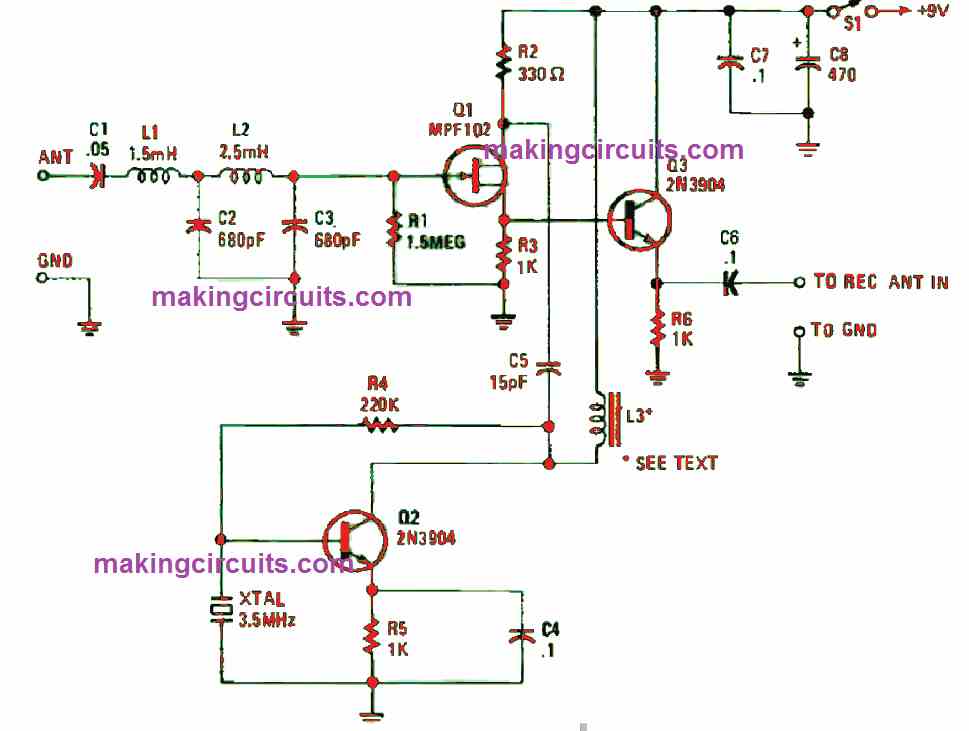
Using the components shown in the circuit diagram above, you can build a circuit which will cover all very low frequencies or the VLF from less than 10 kHz to above 260 kHz.
You need to exchange a few input-filter components if there is a need for the circuit to operate from 200 kHz to 500 kHz. You can remove C2 and C3, and substitute C3 with a 150 pf, 100-WVDC ceramic disc capacitor.
Also, you need to discard L2 and attach L1 to Q1’s gate. Alternatively, if you want to construct only a short-term change, just bridge the connections across L2. Incorporate a standard switching circuit to the swapping methods that were shown if you want a dual-band converter.
Although the circuit’s frequency range is on the low end, you must be careful while building it.
The components are easily mountable on a 2 x 3 inch perfboard. You may also use a circuit board to make the whole unit more compact.
Whatever your circuit configuration is, you must place the components and interconnecting leads short. It is crucial to ensure the crystal-oscillator circuit is isolated from the front-end circuitry.
You can apply a socket for XTAL1 if you need to convert to another frequency. This converter will function most efficient when the unit is enclosed in a metal case. Because the circuit draws a small amount of current (a few milliamps), we recommend the application of a battery.
Before assembling the VLF converter, ensure the connection of the converter’s RF output to the shortwave receiver’s antenna is via a shielded or coaxial cable. It is advised to connect a strong ground to the converter and receiver. After that, you should connect a fairly long wire-antenna to the converter and tune the receiver’s mode switch to the CW position.
The receiver must generate a loud tone through its BFO (beat free oscillator), which is heterodyning with the 3.5 MHz signal from the converter’s crystal-oscillator. When the receiver is regulated above 3.5 MHz and moving towards the 4 MHz mark, the dial value, beginning from 3.5 MHz can be utilized to scan the converted frequency. This means 3.5 MHz = 0 Hz; 3.6 MHz = 100 kHz and 4.0 MHz = 500 kHz.
Inductor L3 was constructed by winding a 26-gauge wire 30 turns on a 0.25-in diameter ferrite core that was retrieved from an old AM-radio, loopstick antenna coil.
You can diversify the range of the VLF converter by changing the crystal’s frequency and L1’s inductance.
When you need to swap from an 80-meter band (around 3.5 MHz) to the 40-meter band (7 MHz), ensure both the crystal and the L3 are replaced.
The value of inductor L3 can be altered to function in the 40-meter band by unwinding around 10 turns.
Parts List
Q1 = MPF102, general-purpose N-channel FET
Q2, Q3 = 2N3904. general-purpose. NPN silicon transistor
R1 =1.5-megohm. 1/4 -watt 5% resistor
R2 = 330-ohm. 1/4 -watt. 5% resistor
R3, R5, R6 = 1000-ohm 1/4 watt 5% resistor
R4 = 220,000-ohm 1/4 watt, 5% resistor
C1 = 0.05-pF. ceramic-disc capacitor
C2, C3 = 680-pF, ceramic-disc capacitor
C4, C6, C7 = 0.1 pF ceramic-disc capacitor
C5 = 15-pF, ceramic-disc capacitor
C8 = 470μE 16-WVDC. electrolytic capacitor
S1 = SPST toggle switch
L1 = 1.5-mH choke
L2 = 2.5-mH choke
L3 = See text
XTAL1 = 3.5-MHz (80-meter band) crystal